Current Regulator Design
The white LEDs have a Vf=3.6V. The bias voltage of the LM334 is >1V. Vbe of Q1 is 0.7V.
Version 1
So the minimum Vdd is 5.3V. This isn't so good.
Do over...
By putting the LEDs and the LM334 in parallel, the minimum Vdd is 3.5+Vr+Vce(sat) or about 3.65V.
This assumes a 3.5V typical LED with 20mA forward current.
But the Itty Bitty Book Light Vol. 2 switch is in the telescoping lamp arm, so there isn't
a way to turn off the bias voltage to the LM334 without adding more circuitry.
Version 2 adds Q3, which is turned on by the voltage across the LEDs (node A_Light). This turns on Q4, which provides the base current for Q2 enabling the bias for the LM334. With greater than 1V across the LM334, it tries to establish 64mV at its reference terminal by pulling enough current from the base of Q1 to cause enough collector current to flow through Rset to make the drop across Rset equal to 64mV. The base current will be about 4 mA. Q2's Vbe(sat) increases with increasing collector current and the current through R7 sets a minimum base current for Q1. The LM334 Iset adds to this current to regulate the current through the LED load.
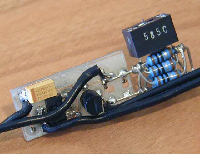
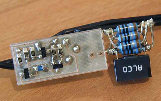
Picture of top side and bottom side of circuit.