Propeller Clock
Design goals
I wanted my propeller clock to display the time on command, so it wouldn't spin continuously. This requires a battery backed real time clock (RTC). I also wanted to implement several display modes including the display of messages and an analog clock. The various display modes were best handled with the LEDs spinning in the same plane.I don't try to correct for the increase in pixel size that results from the increasing circumference of each LED's arc. I chose to limit the code in the processor on the propeller to just be a display processor. When the propeller starts rotating, the display processor needs to be told what to display and what time it is. The control processor provides the battery backed RTC and tells the display processor what to do. It can also use various sensors to control when the propeller starts. Ideally, it can also decide when it is not safe to start the propeller. The spinning propeller is basically invisible and it really hurts when you get in its way.
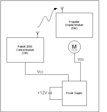
Block Diagram
Display Module (Propeller)
This module must determine where the index position is and controls the timing of the pixels that form the characters in the display fields. There is a top and a bottom display field so the characters are displayed right side up. All timing is interrupt driven. The index generates a capture interrupt that measures the period of rotation. This time is divided by 144 (24 characters of 5 columns with a space separating characters is 24x6=144) using a look up table to determine the individual pixel time. The pixel time is controlled by a timer that generates an interrupt when the time interval has elapsed.
The display module is told what the time is when the propeller is started. The display module must keep track of time until it stops. It uses the index period measurement to keep time by accumulating index periods which are timed with the PIC's crystal oscillator as the time base.
The UART is used for the serial data stream from the RF module. The data rate is 1200 baud. This is the lowest baud rate that can be implemented with a 16 MHz crystal. Serial commands include set_time, clear_top_display, clear_bottom_display, poke, and set_message. The poke command supports setting display modes.
Control Module (CM)
The control module is implemented with a Rabbit2000 core module. The RCM2300 includes 128K flash, 128K ram, 32KHz battery backed RTC, and multiple UARTs. The most important criteria for this application is high level language support. The
development kit includes a C compiler. I chose to port Forth to this platform because most of the protocol for the RF link had been implemented and tested using Forth on a MC68306 single board computer. The Rabbit2000 implementation is smaller and cheaper. The Forth execution is slower, but for this application that doesn't matter.
RF data link
The RF data link between the CM and the DM was implemented with 2.4K bps data rate modules from Reynolds Electronics. Other modules would work too. Consider the Lynx Technologies devices available from Digikey. Look at Lynx application notes AN-00130 Modulation Techniques for low-cost RF Data Links, AN-00232 General Considerations for Sending Data With the LC Series, AN-00160 Considerations for Sending Data with the HP Series.
Transmitter module for CM
Receiver Module for Propeller DM
RadioTronix RCR-433-RP Receiver Data Sheet. It is important to note that the power supply for the receiver must be between 4.5-5.5V and that "this power supply be very quiet" (quote from the data sheet). I tried to acheive less than 10mV of ripple on the receiver's power supply.
Power Supply Module
The power supply is designed to be run from either a 12V battery or a 12VDC power supply. The CM requires 5V at 200mA. The motor is run from Vm, which is adjustable so the speed can be changed. Vm is generated by an LM2941CT in a 5 lead TO-220 package. The LM2941 was chosen because it has an enable. This will allow the CM to turn the propeller on and off. The LM2941 is specified to adjust down to 5.0V and I may run my motor down to Vm=4.5V. To help with thermal dissipation problems in the TO-220 regulators (both Vm and Vcc) I pre-regulate the 12V to 8V using a TO-3 LM317 adjustable regulator. All of these regulators have heatsinks and thermal pads. It is possible to substitute a 9VDC power supply for the 12V supply and the TO-3 LM317 regulator. The motor won't run for long off a 9V ("transistor radio") battery so don't bother.
Design History
My 3rd generation Propeller Clock has a separate controller and display processor. This resulted from poor performance with a battery backed clock on the 2nd generation. The battery life was about 1 month and it was difficult to set the time since the clock interface was a 3 wire serial link. My 1st generation required starting only at 12:00 and running continuously.
The controller circuit implements the battery backed real-time clock and the transmitter for the clock. It determines when to turn the propeller on and what gets displayed by the display processor on the rotor. The communication path between the controller and the display is a unidirectional serial RF link.
For development purposes, it is useful to have an independent interface to another processor. This could be the PSP in a 16F874, or a software UART. The serial data rate is presently 300 baud. A 68K forth board could be used with its second UART channel. The transmit requirements can be handled by an assembly routine that busy
waits on the entire packet, then returns to forth. So forth can assemble a packet, then send it. Once this transmitter is implemented, it becomes easy to debug the display module. Then once the display module is working, the controller can be re-implemented in a PIC, perhaps with a target forth compiler.
Determining when to turn the clock on is a safety issue. The best solution is to have it turn on by command. Sources of command could be IR (say from a hand held computer or a TV remote, however using a TV remote has the problem of having the clock start when the TV is turned on, or #3 is pressed), RF (garage door opener), motion sensing, sound sensing (clap), touch switch, or optical interruption. The most secure, direct control is a touch switch or momentary contact switch. Motion sensing would turn the clock on when someone just passes by (this may be desired in some installations where the clock is on the wall and mechanical interference is unlikely).
The display module needs to respond to commands. First implement set time (it is a clock after all). Then implement text messages. There is no reason to hard code messages.
The receiver is a design by Radiotronix. It responds to OOK signalling. This is not capable of DC levels, so a protocol is implemented. Communication occurs in packets. The packet begins with a preamble that sets the receiver's data threshold. The header is a single character that defines the beginning of data. This is followed by a byte that indicates how many characters will be transmitted. The data field is sent with a last character equal to the checksum of the data field. The final character is a terminator indicating completion. The number of data bytes allows terminator characters to appear in the data field. If the last character received is the terminator and no new characters have been received for the timeout interval and the specified number of characters have not been received, then an error occurred.
The receiver is very sensitive to variation in the power supply. This is somewhat inconvenient since the motor brushes and wiring amount to about 10 ohms (5 on the high side of the circuit and 5 on the low side). The LED bank draws about 200 mA when all are on, so the voltage to the circuit changes by about 2V. The motor spins best at about 6V. A higher voltage results in less time to do display processing and in more acoustic noise. The receiver needs a regulated supply, but the voltage available with resistive loss is insufficient for the 5V requirement of the receiver. The solution is a 50mA LT1514-5 regulated voltage converter.
Vcc Regulation on Propeller
The following scope traces were obtained by fastening the propeller in a vise and allowing the motor body to rotate with long power leads that twisted during the short runs. The motor would be run in the opposite direction to un-twist the power leads.
LT1514-5 switched capacitor regulator
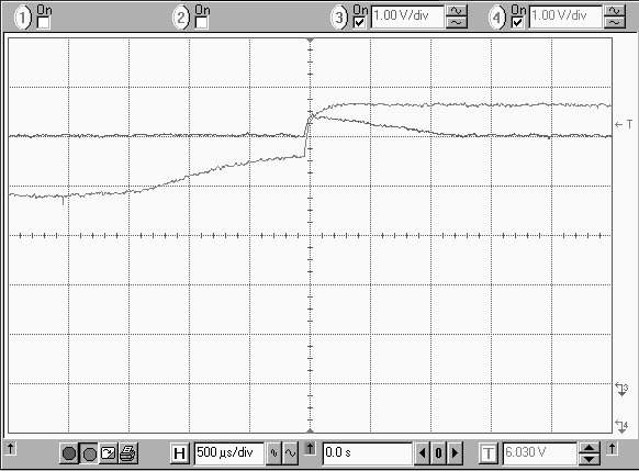
Ch 3: regulator output Ch 4: Vm
Pretty good, but still disturbs receiver.
The next design used a LT1026 doubler followed by linear regulator. This worked, but imposes too high of a minimum Vm because the linear regulator is not a low drop out and the doubler doesn't quite output 2 times the input.
The final solution is a LT1110 switching regulator to produce 8v out for a wide range of inputs (3v..6v) followed by a linear regulator for Vcc at 5v.
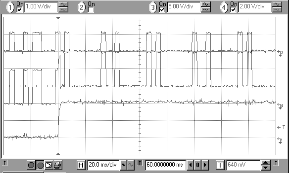
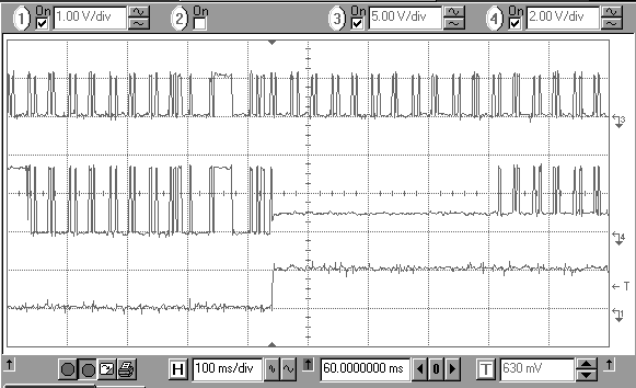
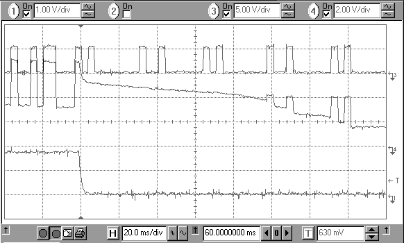
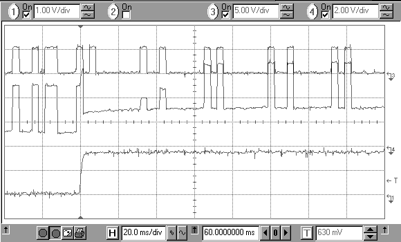
Receiver Dependence on Supply Voltage with Doubler
The following scope traces were obtained by removing the propeller from the motor and holding it in a vise. The variable supply voltage was run through a 10 ohm resistor in the ground lead (to simulate the brush and wiring resistance...somewhat exaggerated). The step seen on channel 1 is due to all the LEDs turning on and off. Channel 1 measures the voltage drop across this resistor. Channel 3 shows the data into the transmitter. Channel 4 shows the data out of the receiver.
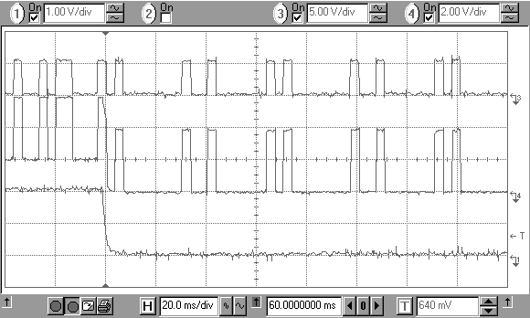
Notice that at Vm = 8.1v there are still dropped data bits. Vm = 9v successfully receives data, but this voltage has the motor spinning way too fast. The analog data output shown in the last pair of traces shows that the shifting ground on the propeller (the high side of the resistor is the propeller's ground) disturbs the receiver's data detection circuit and it takes some time to recover.
RF RX DATA
Vm = 9.0 v
Rs = 10 ohm
ch1: Vrs ch3: tx data ch4: rx data
ch1: Vrs ch3: tx data ch4: rx data
Vm = 6.0 v
Rs = 10 ohm
ch1: Vrs ch3: tx data ch4: rx data
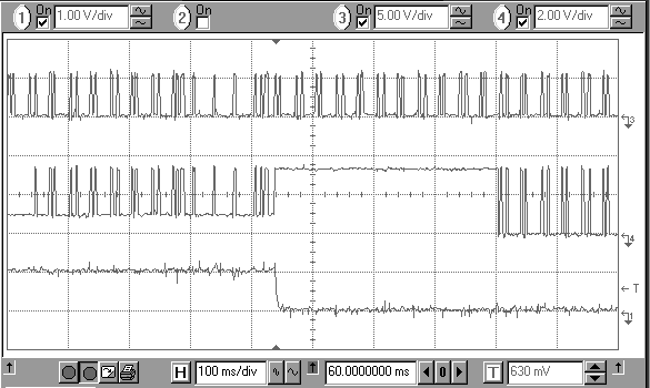
ch1: Vrs ch3: tx data ch4: rx data
Vm = 8.1v
Rs = 10 ohm
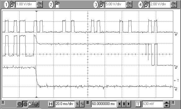
ch1: Vrs ch3: tx data ch4: rx data
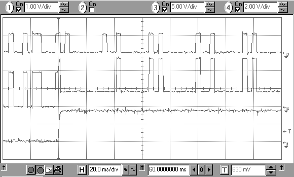
ch1: Vrs ch3: tx data ch4: rx data
RF RX ANALOG
Vm = 8.1v
Rs = 10 ohm
ch1: Vrs ch3: tx data ch4: rx data
ch1: Vrs ch3: tx data ch4: rx data
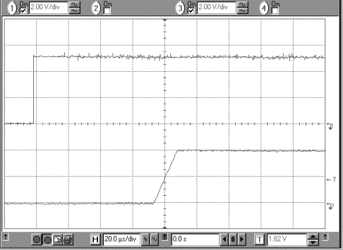
Measured Receiver Performance
Does not work with DC levels...

Ch1: TX data in Ch3: RX data out
Rising edge delay
Ch1: TX data in Ch3: RX data out
Falling edge delay
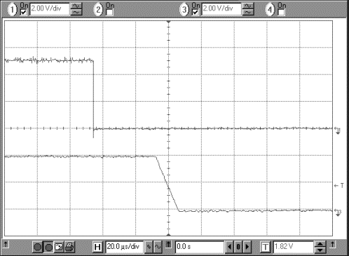
Ch1: TX data in Ch3: RX data out
Voltage (V) |
Current (A) |
RPS (Hz) |
3.95 |
0.16 |
15.0 |
4.34 |
0.18 |
16.5 |
5.01 |
0.21 |
19.0 |
6.03 |
0.27 |
22.5 |
6.49 |
0.30 |
24.0 |
7.02 |
0.34 |
26.0 |
8.21 |
0.42 |
30.0 |
Table 1 Measured motor parameters.
Table 1 data will depend on the rotor and this data was obtained using the rev.3 propeller by reading the voltage and current off a variable bench supply and measuring the frequency of the index pulse from the motor's optical encoder. Note that the motor will spin faster with no load.
R1-2 |
R1-3 |
R1-4 |
R1-5 |
R1-6 |
R1-7 |
1.3W |
2.3W |
2.8W |
2.8W |
2.4W |
1.4W |
Table 2. Armature coil resistances measured between commutators.
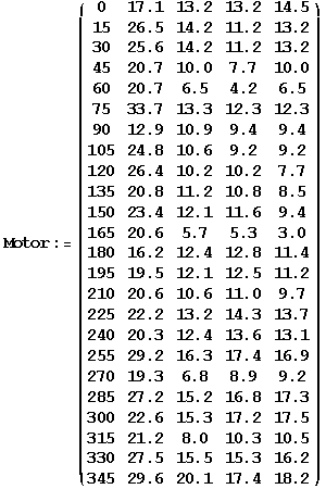
Table 3. Motor lead to lead resistance by shaft postion
The supply wire and brush resistance is 0.1W
The rotating power source is tapped off commutators 1,3,5. Bob's clock had 3 commutators. Mine has 7. I chose not to implement 7 rectifiers and distributed the 3 rectifiers: phase1, skip, phase2, skip, phase3, skip, skip.
Problems and Solutions
* data link (rf, ir, modulated supply)
* rf link is not dc (protocol)
* 10ohm drop in brushes (dc-dc doubler & regulate)
* index jitter (comparator, isr timing, capture)
* min Vm (dc-dc switching converter)
* probe rotating circuit (printf)
* in-circuit program soic (cable)
* high level language CM (rabbit forth)